Eight Pillars Of Excellent FEMI Programs

INTRODUCTION
A refinery or chemical plant Fixed Equipment Mechanical Integrity (FEMI) program consists of eight basic categories or “Pillars” that are fundamental to achieve FEMI excellence. While every refinery or chemical plant has some form of these Pillars in place, they are often inadequately implemented or have significant gaps in the key elements that make up a complete Pillar. This paper describes these Pillars in detail and suggests what distinguishes good Pillars from those that are less than adequate.
| This article has been published previously in Inspectioneering Magazine – 2019 November/December Issue. If you would like to view the PDF of the article, CLICK HERE. |
The Eight Pillars of FEMI are:
- General and Organization
- Resources
- Corrosion Management
- Inspection Planning and Scheduling
- Inspection NDE
- Records
- Recommendations
- Information Technology
Typically, when a FEMI audit is performed for a refinery or chemical plant, each one of these Pillars is reviewed and scored. The following sections provide an overview of the elements each Pillar should contain, as well as criteria for assessing the Pillars in your FEMI program.
GENERAL AND ORGANIZATION
This Pillar is a high-level category that establishes how a pressure equipment integrity (PEI) department functions and is organized. The Pillar is important because it establishes the program culture and demonstrates how much influence the PEI department has within a site. The primary elements of the General and Organization category are organization structure, leadership, working relationships, and standards. Each category will be discussed in detail below.
Organization Structure
Organization structure describes the department in which the pressure equipment inspectors, corrosion and materials engineers (CMEs), and pressure equipment engineers reside. At some sites, these subject matter experts (SMEs) are all in the same department, while at other sites, the inspectors reside in one department and the engineers in another. Typically, the most effective sites have all the SMEs in the same department—but not always. Neither approach prevents a facility from achieving FEMI excellence. Regardless of how department(s) is set up, the defining element of an effective organizational structure is that the groups function as one team, especially when solving problems.
Organization
The PEI department usually reports to maintenance or technical. Either reporting relationship can be effective. The most important issue is the working relationship between the PEI manager and the maintenance or technical manager. The maintenance manager may have a conflict of interest when considering PEI issues. Since maintenance controls the budget and is accountable for the spend, they might not think the value of certain FEMI initiatives outweighs the cost. Whereas, the technical manager isn’t responsible for the overall budget and, as a result, does not usually have the same conflict of interest. However, the maintenance manager usually has a mechanical engineering background, while the technical manager typically comes from the process engineering side. More often than not, the maintenance manager’s background in mechanical leads to a better understanding of PEI issues. To remedy these issues, some companies have made the maintenance manager own the integrity of the equipment, which usually minimizes any conflict of interest. If maintenance does not own equipment integrity and PEI works for maintenance, conflicts of interests will arise.
Leadership
Leadership is usually considered an individual trait that the PEI manager exhibits. While this is important, the organization of the site can greatly contribute to the success of the leader. The PEI manager must have the support of the site’s leadership team, especially the plant manager. If the PEI manager is routinely overruled and not involved in major PEI issues at the leadership team level, the manager’s leadership will erode. Some companies have explicit policies that state the PEI manager has direct communication to the plant manager and has authority to bypass the organization structure if the risk is deemed high enough. Usually, just having these policies in place is enough to deter most rogue managers from making poor decisions in regards to FEMI. The authority allowed by these policies should only be used in extreme cases to assure good working relationships. However, the PEI manager should always have some degree of independence when making decisions and not be overly concerned with costs but should focus on the risk to the site. The term “lives and livelihoods” is a good rule of thumb for the PEI manager to consider when making PEI decisions. Lives and livelihoods generally refer to the roles and responsibilities necessary for minimizing leaks that could lead to:
- Process safety events that may result in loss of life, and
- Reliability events that may result in reduced profitability and potential job losses.
Working Relationships
The PEI department’s most important working relationships are with the maintenance and operations departments. The key interface in both departments is between the PEI unit inspector and the maintenance and operations superintendents of the respective unit. Typically, the PEI unit inspectors must be respected by maintenance and operations such that they are trusted enough to provide good recommendations, which are acted upon accordingly. If the PEI unit inspector is well-respected and works well with both positions, the overall integrity of the unit will be generally positive. However, if the PEI unit inspector does not interface well with the operations superintendent, integrity may erode over time. If the PEI unit inspector does not work well with the maintenance superintendent, work orders may not be executed in a timely manner (or at all), subsequently eroding the integrity of the unit over time. It is important that these two interfaces be nurtured appropriately. These are usually the most important interfaces that affect the PEI culture and performance.
Standards
Most sites have a set of standards or inspection procedures. These documents are usually based on corporate policies and Recognized and Generally Accepted Good Engineering Practices (RAGAGEP) standards and customized to the needs of the individual site. Site standards are sometimes developed with little effort and are not followed very well upon implementation. This is a mistake, because these standards form the basis of the PEI culture at a site. A well-developed set of procedures that are owned by the unit inspectors is the basis for PEI culture. Managers and organizations come and go, but the inspection procedures will remain. Many times, if the PEI culture is poor, the root cause may be a lack of well-understood, comprehensive inspection procedures. Typically, there is a base of seven core procedures necessary to assure compliance and upwards of 50+ additional procedures to aspire toward excellence. A listing of the base seven procedures to assure compliance is listed below:
- Fixed Equipment Integrity General Expectations
- Deficiency Resolution for Fixed Equipment
- Fixed Equipment Inspection Intervals
- Fixed Equipment Integrity Metrics
- Pressure Equipment Inspection
- Piping Systems Inspection
- Atmospheric Storage Tank Inspection
A detailed description of compliance standards and a listing of excellence standards will be presented in a future Inspectioneering Journal article.
RESOURCES
The staffing level and budget for the PEI department is an important factor regarding the department’s effectiveness. The unit inspector is the key resource for an effective department. In my experience, I’ve found that a unit inspector can, typically, only effectively manage 300 pieces of pressure equipment (this does not include PRVs or ASTs). Above 300, the unit inspector may be overwhelmed just handling the turnaround planning and routine maintenance day-to-day workload. Experienced unit inspectors with a good support staff may be able to effectively handle up to 350 pieces of pressure equipment, but effectiveness diminishes above that number.
In addition to the unit inspectors, the site should have CMEs on staff. Typically, a small refinery (less than 100,000 BPD) can be effectively handled with one CME. However, a complex medium size refinery (200,000 BPD) will typically need 2 CMEs. The best CMEs are proactive and work together with the unit inspector by being in the field and supporting the unit inspector on turnarounds and complex corrosion problems. If overloaded, the CME will simply be a consultant and wait for unit inspectors to ask questions.
Another key SME is the fixed equipment engineer. All sites usually have multiple fixed equipment engineers, but they may not be in the PEI department. Pressure equipment code calculations are a key skill set for any refinery. Other important SMEs those refineries should have access to are: ASNT Level III inspectors, welding engineers, coatings experts, and quality assurance and quality control inspectors. If a site does not have adequate access to these specialty SMEs, the site will typically default to maintenance staff or contractors. This often leads to poor results due to lack of experience and qualifications.
Budgets are a key indicator on how well the refinery supports the FEMI program. The PEI department will typically have to utilize a large amount of contractor support—primarily nondestructive examination (NDE) technicians—to be effective. If the budget is too small, the refinery will likely be out of compliance for a basic level of inspection
Finally, the site should have a training plan developed for each person. Key positions should also have a succession plan to assure technology will be available to the refinery on a sustain-able basis. The training can consist of corporate, industry, or on the job training. Most of the SMEs should have the opportunity to attend ASME, API, or NACE meetings on a routine basis in order to stay connected and abreast of industry trends and emerging technologies.
CORROSION MANAGEMENT
The Corrosion Management System is the heart of any best in class mechanical integrity program. The basic function of the Corrosion Management System is the identification of all of the damage mechanisms in a specific unit and the location in pres-sure vessels and piping where the damage mechanisms will occur. The current state of corrosion engineering expertise and available NDE tools allow for accurate identification of damage mechanisms (both initially and ongoing as corrosion activity continues to be inspected in a process unit). There are very few damage mechanisms that are not well-known and documented accordingly. The most diff cult part is determining the exact location of the damage mechanism in the specific unit. After the location is identified, the area should be inspected with the right NDE technology. There is usually some degree of uncertainty when identifying the exact location of damage. Therefore, the NDE must be able to adequately find the specific location of damage before corrective action can be taken.
Setting up the Corrosion Management System is a challenge and takes considerable resources. A typical system is shown in Figure 1.
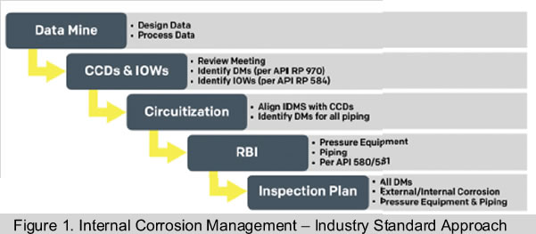
There are five major components to setting up a Corrosion Management System. Each of which will be addressed in detail below. They are as follows:
- Data Mining
- Damage Mechanism Identification and Control (CCD’s & IOW’s)
- Piping Circuitization
- Risk-Based Inspection
- Inspection Planning
Data Mining
In order to identify damage mechanisms, data must be obtained and organized in a logical manner. The specific type of data consists of the following three categories: design data, process data, and inspection data. The data is usually stored in an electronic library, in addition to paper copies in a filing system. The industry has become very efficient at extracting this information by using optical scanners, spreadsheets, and data loaders. Approximately 30-60 pieces of specific data are required for each pressure vessel and piping component. This effort is labor-intensive and costly and may be the largest hurdle in setting up a Corrosion Management System.
Damage Mechanism Identification and Control
Data mining allows an experienced corrosion engineer to identify all of the damage mechanisms and locations where the damage is likely to occur. The data is typically displayed on a P&ID, PFD, or, preferably, a Corrosion and Materials Diagram (CMD). Usually, a corrosion review meeting takes place and includes personnel from process engineering, operations, inspection, and engineering to assist the corrosion engineer in this work. The meeting is sometimes referred to as a Damage Mechanism Review (DMR). In some jurisdictions, the DMR is a legal requirement much like a HAZOP review. The meeting is usually documented in a Corrosion Control Document (CCD). Specific requirements for a CCD are found in API RP 970, Corrosion Control Documents. Additionally, during the DMR, the corrosion engineer will identify the operating limits to prevent corrosion from occurring. These limits are referred to as Integrity Operating Windows (IOWs). The specific requirements for IOWs can be found in API RP 584, Integrity Operating Windows.
Circuitization
Circuitization is the process of identifying the exact location of the damage mechanisms in a specific unit. Specific damage mechanisms typically occur in specific areas of a process unit based on the process conditions. These areas include pressure equipment and piping and are sometimes referred to as corrosion loops or systems. Systems are further broken into specific pieces of piping and pressure vessels called circuits; hence, the term circuitization. These circuits should be accessible in electronic drawings with the appropriate damage mechanisms shown. Usually, inspection isometrics are used for the documentation of this step. Since approximately 90% of leaks occur in piping (based on my experience reviewing leak data for many sites), developing detailed piping drawings should be the first step to inspect for corrosion activity. This step is costly and time-consuming, but it is necessary to have a pro-active, sustainable system.
Risk-Based Inspection (RBI)
The next step is to determine the intervals of inspection. This can be done using predefined rule-time-based intervals as prescribed in various codes or by utilizing Risk-Based Inspection (RBI). Many papers have been written about RBI and there are two API documents available that describe the details: API RP 580 and API RP 581. RBI is not necessary for an effective program. API 510 and 570 define time-based approaches to inspection and have specific rules for establishing intervals. However, most of the industry is using RBI, primarily because it often allows for longer inspection intervals for pressure vessels, which, in turn, saves turnaround costs. If a site or company decides not to utilize RBI, they may become non-competitive with other companies over the long-term. RBI can also be utilized for piping, but few operators use RBI to set piping inspection intervals. Instead of risk, half-life and corrosion rates via the Inspection Data Management System (IDMS) is a more cost-effective method for establishing piping inspection intervals.
Inspection Planning
Inspection planning is the final and most important step when setting up a Corrosion Management System. All of the work from the previous steps is transferred to an actual inspection plan that can be executed in the field. Spreadsheets are a poor substitute for a well-laid-out electronic inspection plan. Most IDMS software packages have inspection planning modules or a report writing system in which such a plan can be developed. It is important that the plan is detailed enough to execute in the field. Regarding piping, a Corrosion Monitoring Location (CML) allocation procedure will typically need to be developed. This procedure should include the NDE technique required and the location and number of CMLs, as well as all external and internal damage mechanisms.
INSPECTION PLANNING AND SCHEDULING
A good Corrosion Management System, as described above, should produce high quality inspection plans as the final output. The plans should identify all damage mechanisms, including external mechanisms. The piping plans should include the appropriate level of CML allocation based on the damage mechanisms identified.
Inspection Planning
Inspection planning consists of two distinct areas: routine maintenance and turnaround planning. Generally, most pressure vessel internal inspections occur during turnarounds and most piping CML inspections occur during routine maintenance activities while the unit is running. A key component to inspection planning is the inspection interval. As mentioned above, intervals may be set using a time-based or risk-based approach. Typically, pressure vessel inspections are more cost advantageous under a risk-based approach – as intervals are usually longer for approximately 80% of the pressure vessels; therefore, reducing turnaround costs. Most sites have some form of risk-based approach in operation for pressure vessels. Piping, on the other hand, may be more efficiently inspected using a time-based approach. As an example, an API 570 Class I line requires a visual external and thickness measurement inspection at least every five years, regardless of damage mechanism or corrosion rate. Piping inspection CMLs are typically driven by the IDMS, which is based on half-life and corrosion rates. If there is a corrosion rate, the IDMS system will typically recommend a thickness measurement much less than 5 years. There may be very little advantage in utilizing a risk-based interval for piping, as RBI will not typically recommend an interval that is much longer or shorter than the time-based approach. However, some sites consider risk-based intervals advantageous because high-risk piping may be identified, and subsequent inspections may occur, lowering overall risks. A time-based approach using only corrosion rates may miss a high-risk piece of piping.
Overdues and Deferrals
A key driver of inspection planning is overdue inspections (“overdues” for short). Most sites attempt to operate with near zero overdues of pressure equipment and piping. In order to succeed in this effort, the overdues should be tracked on a monthly basis. This tracking should be part of an overall set of Key Performance Indicators (KPIs) and should be reviewed by the site’s inspection department and leadership team. Monthly reviews are most beneficial, but quarterly may also be effective. In order to avoid overdues, equipment inspections must be deferred from time to time due to operational upsets and maintenance availability. Deferring equipment is an acceptable practice if a site justification procedure and work process is rigorously followed. Tracking the number and type of deferrals is also part of the overall set of KPIs tracked by the site.
Maintenance
Routine and turnaround maintenance personnel typically schedule and support the inspection of pressure equipment and piping. Maintenance provides scaffolding, insulation removal, safety support, surface preparation, and permitting. The relationship between the maintenance and inspection departments is one of the most important working relationships at a site. It is important that inspectors and the inspection department manager work with maintenance effectively.
INSPECTION AND NDE
The PEI department is responsible for inspecting equipment. In order to perform that duty, there are typically three types of inspectors needed as listed below:
- Unit Inspectors
- Contract NDE Inspectors
- Contract API Inspectors
Unit inspectors are the primary resource and have the responsibility to inspect the equipment. The unit inspector is typically required to have API certifications for API 510 (for pressure vessels), 570 (for piping), and 653 (for tanks) as the minimum credentials. The unit inspector is responsible for (whether performing or approving) equipment inspections in the unit and is the representative of the PEI department for the unit’s operations and maintenance personnel.
Many of the inspections require specialized skills, such as ASNT UT/RT/MT/PT/VT certifications and safety training, for handling certain NDE equipment. Unit inspectors don’t normally possess these specialized skills or certifications. In these cases, support is often contracted through NDE companies that specialize in this area. However, unit inspectors typically perform the NDE function on a case-by-case basis at some sites and have ultimate responsibility for the quality of inspections.
To assist the unit inspectors, contract API certified inspectors are also utilized, especially during turnarounds. These contract inspectors are also brought in to carry out special emphasis programs (SEPs) during routine operations. Many of these types of inspectors were previously unit inspectors and have a large amount of experience.
Inspection Tools
Inspections require tools. The most common are ultrasonics and radiographic. There are many specialized tools in these areas and numerous publications are devoted to when and where they should be used. The most important information is the applicability and accuracy of a tool given a specific damage mechanism. Using the wrong NDE tool will provide poor data, which leads to poor decisions. It is important that at least one of the unit inspectors has experience with the various NDE tools to provide good advice. Third party experts are also available and can provide good advice to a site. Many times, NDE suppliers are driven by sales, not necessarily providing the best NDE solution. The buyer of the NDE services needs to be aware of this and able to sniff out misleading sales, should the case arise.
Special Emphasis Programs (SEPs)
Routine and turnaround-related inspections make up most of the inspection work, but SEPs should also be in place where appropriate. SEPs are inspection-related projects or campaigns that are funded outside of routine and turnaround work. A listing of typical special emphasis programs is shown below:
- Corrosion Under Insulation (CUI)
- Mechanical Devices (PRVs, critical valves, spring cans, hoses, loading arms)
- Heaters
- Underground Piping
- Injection Points and Mix Points
- Deadlegs
- Soil-to-Air Interfaces
- Small Bore Piping
- Rotating Equipment
- Flare Equipment
- Structural
RECORDS
Inspection Data Management System (IDMS)
The most important record keeping system for an inspection department is the IDMS. It houses all of the thickness data, visual inspection reports, and any special inspection reports, such as scans, crack sizing, and calculations. The IDMS is the primary working tool for the unit inspector.
There are several companies that sell or license their own version of the IDMS. A good IDMS will be set up accordingly for the specific site and customized to some degree. Typically, “out-of-the-box” programs have limited use, as they don’t account for all of the processes and nuances specific to the site. So, efforts and costs to customize the software to match the site’s specific requirements are usually justified.
One important area to consider is the quality of thickness data. Many times, thickness data is entered into the IDMS without quality assurance/quality control (QA/QC), which can lead to data with growths and errors and results in corrupted data. Good thickness data can produce accurate corrosion rates. Accurate corrosion rates are very important when predicting damage rates, as these will contribute to determining the next inspection and/ or remaining life. A short-rate is the corrosion rate since the last point taken and may vary somewhat. A long-rate is the average corrosion rate over several points and is typically considered more accurate. If the data is of poor quality, the corrosion rates (whether short or long) are meaningless. A site should take sufficient measures to clean up poor data with a growth and error review when necessary.
Fixed Equipment Library
A site should have a fixed equipment library to house important records, studies, books, etc. Most sites have all of the information online, but there are often gaps in the electronic record systems. Record systems at some sites have been seriously degraded when the change to a fully electronic record systems occurred, and records had to be rebuilt from scratch.
At a minimum, consideration should be given to house the code documents, including U-1s and R-1s, in a paper system and electronic system. When a pressure vessel is modified and an R-1 is issued, there can be large amounts of back-up paper information, such as Material Test Reports, heat treatment records, hydrotest records, and calculations. Sometimes this data does not make it into the electronic system and important information is lost.
Other types of information that are typically included in a library include code books, reference books, welding procedures, and fitness-for-service (FFS) calculations.
RECOMMENDATIONS
Quality Assurance/Quality Control
In my experience, approximately 10%-20% of all leaks are the result of poor-quality workmanship. Maintaining a robust QA/QC program is typically the responsibility of the PEI department. The three main components of a QA/QC program are turnarounds, routine maintenance, and projects (including shop and field tie-in inspections). In order to execute a program, a detailed QA/ QC manual for pressure equipment, piping, and tanks should be developed. A traveler system should also be included in the manual to track the equipment through fabrication and installation. Experience has shown that haphazard systems will not reduce or eliminate leaks. For projects and turnaround-type work, it is generally easier to implement a robust QA/QC program, as routine maintenance usually relies on the craftsman to perform much of their own quality checks due to the high daily volume of work.
A Computerized Maintenance Management System (CMMS) is the backbone of any QA/QC program. The QA/QC program should be well-integrated in the CMMS work order system and tracked accordingly. The CMMS should also track all overdues and deferrals of FEMI-related work orders. Some sites have resorted to building a separate tracking system for FEMI-related work orders because of a lack of trust between maintenance/operations and the inspection department.
Action Item Tracking
The PEI department typically gets assigned action items from management of change (MOC) requests, HAZOPs, and other reviews and audits. These action items can be numerous and difficult to track. A site usually has a MOC tracking system but not necessarily a HAZOP or audit tracking system. Many times, spreadsheets are used as a last resort. This will typically lead to action items being dropped, which results in overall increased risk for the site. The PEI department should take a lead role working with Process Safety to develop a robust tracking system for all action items. The tracking system should include a methodology for assigning and tracking FEMI-related risks.
INFORMATION TECHNOLOGY
The final Pillar of an excellent FEMI program involves information technology. This is related to Records (Pillar VI) but goes well beyond the maintenance of data. At a minimum, the site should have a complete electronic record system to house all FEMI related documents. The system should be kept up to date and well organized. Generally, a separate department maintains this system which is used by all departments at a site.
There are two key components that should be implemented. The first is the electronic linkage between the CMMS and IDMS. The IDMS generates FEMI work requests and should contain all of the technical requirements. The IDMS passes the information to the CMMS which turns the information into field work requests with the appropriate schedule, priority, permits, and funding. The second key component is a linkage between the IDMS and the selected RBI program. There is a significant amount of data that passes between these two programs and it has been proven time and time again that a manual system of data transfer is not sustainable. Fortunately, commercially available IDMS solutions include embedded RBI programs which make the data transfer seamless.
CONCLUSION
Achieving FEMI excellence at a refinery or chemical plant is dependent upon many factors. These factors are described in this article as the “8 Pillars.” Many times, a site will emphasize one Pillar at the expense of others. As an example, the Corrosion Control Pillar is one that is generally pursued with high priority. However, if the Organization Structure and Resources are not set up appropriately, the corrosion control effort may not be successful. FEMI departments have limited budgets (especially for improvement efforts), but over-emphasizing one Pillar may not be a successful practice. Developing all of the Pillars to some degree is necessary to achieve excellence in Fixed Equipment Mechanical Integrity.
If you would like to ask a question or leave a comment for the author, you may add it at the bottom of this page. If you would like to contact Becht about a technical issue or learn more about their services,