Resolution of Chronic Cooling Tower Fan Vibrations
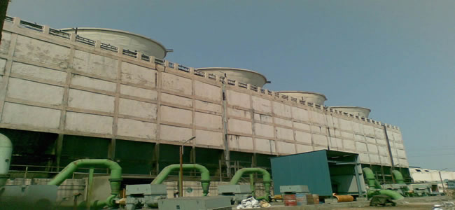
Traditional rotating equipment mounted at grade use the mass of a foundation and grout to reduce vibration and provide support and stiffness. However, cooling tower fans must be elevated many feet above a basin of water which sometimes puts them “out of sight and out of mind”. Cost and practicality prohibits concrete and grout, thus most cooling towers are constructed by bolted wood and / or fiberglass elements with a fabricated steel sub base supporting motor, gearbox, and blades. As a result, cooling tower foundations are much less stiff than traditional rotating equipment. This is usually not an issue because the low speed of the fan (usually 60 rpm to 140 rpm) does not usually produce large forces. Motors and gearboxes used are generally made to the same precision levels as other general purpose machinery regarding balance, runout and dimensional tolerances, so the imbalance and forcing functions are usually low. As long as the motor and gearbox are properly aligned, the fan blades are balanced and pitched at the same angles, and there is no structural looseness or resonances within the operating speed range, the unit will operate many years with acceptable vibration levels.
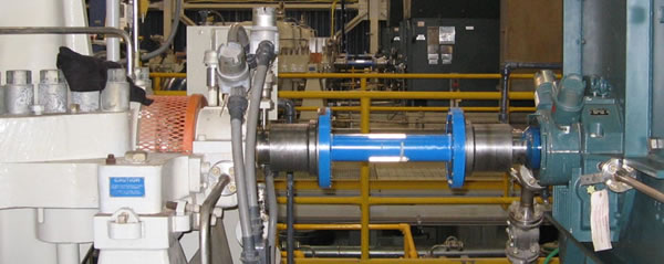
At a gulf coast facility one cooling tower fan experienced elevated vibration levels from the day it was commissioned. It used 6 fiberglass blades with a tip to tip diameter of approximately 30 feet driven by a variable speed motor connected to a right angle drive gearbox through a 184” long flexible coupling. As vibration levels slowly increased over time, alert and trip levels were gradually raised to 0.75 ips 0-pk and 0.9 ips 0-pk respectively to allow continued operation. At available outages, motor to gearbox alignment was performed, blade tracking and pitch was checked and structural elements were replaced and loose connections tightened. This resulted in lowered vibration levels which would again increase over time. Foundation supports constructed from bolted wood connections can accept forces up to a point and still provide a rigid connection. Above that point the wood begins to yield and the joint becomes loose. This produces more vibration which leads to further loosening.
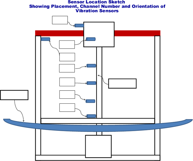
During an outage of the fan in 2014, a vibration analysis was performed by Becht Engineering. Eight (8) sensors were installed at select locations of the support structure inside the stack. The unit was placed in service and run through the operating speed range from 0 rpm to 135 rpm over a 10 minute period, while a vibration analyzer recorded data to disk for post processing and analysis. Values up to 0.8 ips 0-pk were measured and recorded. Amplitude and phase readings indicated severe structural looseness between the steel foundation and the wooden members. One key vertical 4” by 4” support was extremely loose and the fan and hub assembly was out of balance. Vibration levels due to imbalance usually increase with the square of the speed change (raise speed by factor of 2 and vibration increases by factor of 4). Any values above this rate of change can be an indication of a resonance in the system being excited. This was experienced in this case where a fan speed change from 87 rpm to 95 rpm resulted in a vibration increase from 0.4 to 0.7 ips 0-pk.
A plan was developed for future work to eliminate the excessive vibration and find the cause of the large amplitude change between 87 and 95 rpm. This plan was executed during an outage approximately 15 months later. Becht Engineering was requested to participate in the customers planning and execution process to help identify task durations, necessary material and resources, as well as eliminate conflicts in order to minimize the duration of the outage. Major work items are listed below:
- Tighten and reinforce the structural members under the foundation.
- Install a new gearbox and coupling.
- Install 6 new blades following the steps below. A fan can always be balanced in place if necessary but by simply following the steps below a precision installation should result.
- “Moment weigh” all 6 blades and construct an assembly diagram to insure opposing blades have closest moment possible. This is an important and often overlooked step in assembly. Blade manufacturers have greatly improved their blade quality over the years and the weight of each blade is usually stamped on the blade. Most craftsmen think that as long as they are all the same weight it makes no difference where they are installed on the hub. This is wrong and makes no allowance for how the mass is distributed along the length of the blade. If two blades of equal weight are installed 180 degrees away from each other on the hub and 1 blade has more weight concentrated at the tip of the blade and the other has more weight concentrated toward the hub end of the blade, an unbalance force will result. To prevent this, each blade should be individually placed across a bar or knife edge perpendicular to the blade and the blade moved along its length until it is balanced and does not tip toward either end. A measurement should be taken and recorded from the pivot point to the shoulder that seats in the hub clamp. The blades with the closest measurement should be placed 180 degrees opposite each other when assembled.
- When assembling blades in clamping collars, insure that shoulder on blade fit is against shoulder in collar before tightening.
- Insure that pitch angle is correct and identical for all 6 blades. The blades are designed for optimum flow at the specified pitch angle. Any 1 blade pitched differently will cause a 1 times rpm force on the unit resulting in vibration.
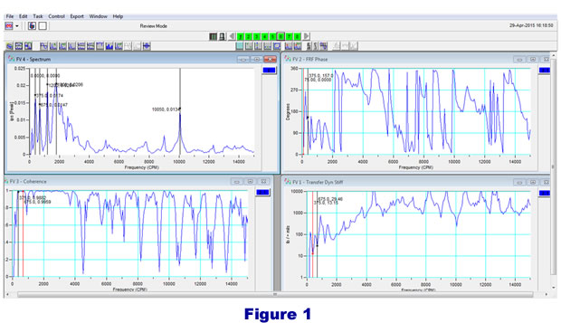
After the repairs were completed, impact testing of the motor / gearbox foundation and supports was performed to determine if any natural frequencies existed within the speed range of the fan (see Figure 1). The structure was impacted with a force hammer in the horizontal direction and the data plotted is from the vertical support about 8 feet west of the gearbox in the east west horizontal direction. The dynamic stiffness plot at bottom right shows responses at 375 cpm, 675 cpm and 1200 cpm. At bottom left is a coherence plot showing excellent coherence at the natural frequencies listed (a coherence of 1 indicates that the sensor response is due entirely from the hammer). Amplification factor at the 675 resonance is calculated at 4.6, which is typical for a wooden structure. At fan output speeds of 46% (62 rpm) and 80% (108 rpm) blade pass frequencies of 375 cpm and 675 cpm respectively would coincide with the natural frequencies (62 rpm X 6 blades=372 cpm. 108 rpm X 6 blades=~675 cpm).
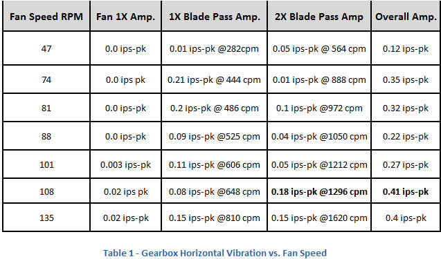
Upon startup of the unit, vibration levels were reduced from the previous range of 0.4 – 0.8 ips to values ranging between 0.2 and 0.4 ips (see Table 1 below). As can be seen in the column “Fan 1X Amp.”, fan speed vibration was not even measurable until the unit reached 101 rpm. The overall vibration amplitude of 0.4 ips at 108 rpm fan speed was considered high. Upon investigation it was found that the structural natural frequency at 1200 cpm was being excited by energy at 2 times blade pass frequency (108 rpm fan speed) X (6 blades) X (2) = 1296 cpm (see Figure 2). Since the speed of the fan was automatically controlled by a process variable, the DCS output was configured to avoid set points between 105 rpm and 111 rpm. The unit is now running reliably below 0.4 ips.
Figure 2 below shows data taken at 80% speed. At top left the overall vibration level is shown as 0.46 ips-pk. Bottom right time waveform of tach signal shows a blade pass frequency of 668 cpm. The spectrum at bottom left and the time plot at top right show the 1X and 2X blade pass amplitudes.
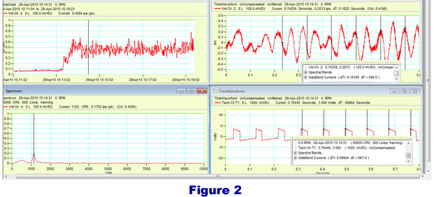
Table 1 below presents vibration amplitudes upon start up at fan rotational speed, 1X and 2X blade pass frequency and overall vibration.