Submitting an FEA Report to ABSA
The pressure vessel and piping jurisdiction in Alberta, Canada is ABSA – the pressure equipment safety authority. All pressure equipment as defined by the provincial Safety Codes Act must be registered with ABSA. I have been involved in registering piping systems and pressure vessels in this, my home jurisdiction.
The focus of this blog post is what is required when you use an FEA to assist in the justification of your design.
Based on my experience, ABSA’s preference is to have designs justified using Design-By-Rules. Therefore, in piping or pressure vessels, if there are rules in one of ASME Section VIII, Divisions 1 or 2 or ASME B31.3, then that is their preference. However, there are many situations where the specific geometry or loads are not explicitly covered by the rules. This may require a Design-By-Analysis. Note that these rules also apply to Fitness-For-Service FEA reports.
Although there may be many methods that could fall under Design-By-Analysis, it typically refers to finite element analysis (FEA). FEA is a special methodology that discretizes a continuum into small “elements”, the mathematical equations of which are well understood, and combines these elements to simulate the actual structure. Owing to the specialized nature of FEA, ABSA has created a document that provides rules for the resulting report. Although these requirements apply strictly to the report, I contend that they are intended to provide guidance to how the FEA is performed.
This document – AB-520 (Click) – is available on the ABSA website.
FEA Submission Requirements
AB-520 starts by reinforcing that FEA may be used where there are not rules already present. ABSA recommends that the designer check with ABSA prior to the design submission to determine whether the use of FEA is acceptable. Based on my experience, this is extremely important and should be done early in the design stage – good documentation of the discussion is a must. Also, the report must explicitly indicate how the design is NOT covered by the rules. For example, for an ASME Section VIII, Division 1 vessel, the designer must show how the geometry or loads are not explicitly covered by rules, and the report must explicitly state that article U-2(g) is being activated.
Special Design Requirement
ABSA requires that the analysis and report be completed, certified and signed off (stamped) by a Professional Engineer registered in the US or Canada. BUT, not any PE/P.Eng. can certify the report: they must be experienced in pressure equipment design and the application of FEA. In fact, ABSA may request that the Professional Engineer provide a summary of qualifications and experience.
Executive Summary
Although this should be standard practice, ABSA requires an Executive Summary that briefly describes how the FEA was used to support the design, the FEA model, the results and conclusions.
Introduction
ABSA requires an Introduction section that lays out several items, including:
– Scope of the FEA
– Justification for using FEA (see the discussion above about, for example, U-2(g))
– The FEA software (including the version used)
– The type of analysis (linear elastic, elastic-plastic, etc)
– Material Properties. A complete description must be provided. Simply referring to a material specification is not sufficient. All of the material properties used must be presented. I recommend that a mixture of tabular data as well as graphical data be used to efficiently provide this data – especially if material properties as a function of temperature are used.
Model Description
AB-520 is very focused on providing appropriate descriptions of the FE models. There are many requirements provided. I won´t get into all of these requirements as they are well listed. I will highlight a few important items.
Dimensional descriptions should be provided – in fact all appropriate drawings should be referenced. I would recommend that some critical dimensions be explicitly described in the report, because this is something that the Design Survey Engineer at ABSA can check. If there are any geometric simplifications used, those also need to be discussed and justified. The order of the elements should also be reported. Such design features as the number of elements on fillet radii should also be reported. I would also include such items as the number of elements in the through-thickness direction for 3D-solid models.
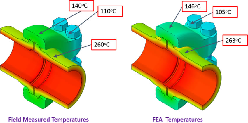
There should be a significant description of the mesh, particularly the mesh size. AB-520 requires that the accuracy of the model by way of the discretization be indicated. A convergence study is expected – although it is not explicitly required for every FEA. Even more importantly, the report must include a proposed method to verify the model results with the physical equipment.
Of course, boundary conditions and loads must also be detailed. When symmetry is used, its use must be justified. I would recommend that symmetry models NOT be used when performing buckling calculations.
Presentation of Results
ABSA wants the following results
- Displacements
- Deformed shape with un-deformed shape superimposed
- Stress plot with the mesh
- Show discrete colour separation (not a continuous colour plot)
- Show a comparison between stress concentrations and the mesh size
- Plot a comparison between the average and un-averaged stresses (element vs. nodal)
- Reaction forces compared to applied loads
Analysis of Results and Conclusion
AB-520 has no additional requirements for discussing the analysis of the results. In my opinion, this is a huge deficiency. That said, I would recommend that this section of the report follow the approach in ASME Section VIII, Division 2, Part 5. (I will be posting another blog post on applying Part 5 for U-2(g) for ASME Section VIII, Division 1 vessels that will address this topic more).
Although AB-520 does not provide additional guidance on this topic, based on my experience, I recommend that when you follow the rules of Part 5, you should be well covered. That said, the ABSA Design Survey engineers do not have much practical experience in applying Part 5 and FEA, so the presentation of the results should be as simple and clear as possible. ABSA definitely does not want to see hundreds of FEA stress plots. Only present those results specifically relevant to the conclusions.
In general, all of the above requirements should be presented in paragraph-form. I recommend that ALL figures be referenced in the text of the report – if they cannot be referenced, perhaps they are not important/relevant. I would tend to think that even a long and complicated FEA report should not be longer than 45 pages. Conversely, even a simple report will likely be 12 pages long, just to satisfy the requirements listed above. Definitely don’t submit a 5 pages report with 100+ pages of figures.
My experience has been that the ABSA Design Survey engineers are very knowledgeable about pressure equipment design rules. They have some knowledge about FEA – mostly enough to detect BS – but likely less than the typical FEA specialist. However, if the FEA report is clear, concise yet descriptive, and well written, then there shouldn’t be problems. My only issues have been regarding whether FEA could be used – and whether Code Rules are applicable. When you discuss these issues with ABSA prior to the design submission, these problems can be avoided.


It has been brought to my attention that the link to the AB-520 has changed. The new link is http://www.absa.ca/wp-content/uploads/2016/02/AB-520-Finite-Element-Analysis-FEA-Requirements.pdf
Note that effective in 2015, all Provinces and Territories in Canada are required to follow essentially the same rules, because these rules have been written into CSA B51 (Annex J).