Brittle Fracture Resistance Workbook API 579-1/ASME FFS-1 Approach (Fitness-For-Service)
Description
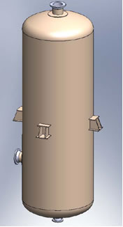 Process vessels such as towers, drums and heat exchangers may be exposed to low temperatures as a part of normal operation or as the result of an upset condition. Carbon and low alloy steels typically used in process vessels undergo a transition from ductile to brittle behavior as temperature is reduced and are at increased risk of brittle fracture at low temperature. To reduce this risk, the ASME Boiler & Pressure Vessel Code contains requirements for vessels and vessel components with respect to low temperature operation. While these rules are applicable to new construction, API 579-1/ASME FFS-1 Fitness-For-Service uses the Code rules as the basis for evaluating the brittle fracture resistance of existing vessels. This article discusses an approach and spreadsheet tool that was used to provide a client with operating pressure limits as a function of decreasing vessel metal temperature. These limits were used as part of the client’s process hazard analysis to set operating pressure guidelines for process vessels identified as having the potential for low temperature excursions as a result of the auto-refrigeration of light liquid hydrocarbons.
The design temperature of process vessels constructed prior to 1987 typically used the expected operating temperature plus some margin above or below that temperature as the design temperature. The Code permitted the use of carbon and low alloy steels to –20F without the need for impact testing which provides a measure of a steel’s resistance to brittle fracture. For operating temperatures below –20F there were additional material requirements including impact testing. After 1987, the Code implemented new rules including the elimination of impact testing exemption to –20F and implemented the concept of Minimum Design Metal Temperature (MDMT). In setting the MDMT, the Code requires that “consideration shall include the lowest operating temperature, operational upsets, auto-refrigeration, atmospheric temperature and any other source of cooling.” For equipment constructed prior to 1987 where operational upsets or auto-refrigeration may not have been considered, the API 579-1/ASME FFS-1 procedure can be used to assess the risk of brittle fracture and for setting operating pressure limits.
API 579-1/ASME FFS-1 methodology provides for three levels of assessment with each level progressively more in depth and requiring more information. Level 1 is used for evaluating equipment meeting toughness requirements of a recognized code or standard and usually can be accomplished through a review of equipment records. Level 2 is divided into three methods (A, B, and C) that take into account not only the materials of construction but material heat treatment, design stress, postweld heat treatment, hydrotest pressure and temperature, service environment, and past and future operating conditions. Level 3 is used for equipment not meeting acceptance criteria for Levels 1 and 2 and typically involves in-depth analysis using fracture mechanics. The objective of the various levels is to determine the acceptability of the equipment for operation at a given pressure and temperature or an envelope of pressures and temperatures.
In the case of auto-refrigeration that occurs on rapid depressurization of a vessel containing a light liquid hydrocarbon, the temperature will follow the vapor pressure curve and may drop below the MDMT for the vessel if auto-refrigeration was not a design consideration. In the discussion below, we will consider process vessels constructed prior to 1987, i.e., prior to implementation of the MDMT concept. API 579-1/ASME FFS-1 defines a material’s minimum allowable temperature (MAT) as the permissible lower metal temperature limit for a given material and thickness based on its resistance to brittle fracture. The MAT may be a single temperature or an envelope of operating temperatures as a function of pressure. To establish the MAT it is necessary to have information on the mechanical design and material specification for the process vessel.
Fluid vapor pressure data and vessel information (drawings, calculations, and material specifications/data) are usually readily available. Establishing the MAT is somewhat more complex in that API 579-1/ASME FFS-1 has different levels of assessment as previously discussed and related charts and equations that guide the user through the process of establishing the MAT. In the case of a process vessel there will be a “limiting” component, e.g., shell, head, skirt, nozzle, flange, tray support, tubesheet, etc. that will set the MAT for the vessel. For example, a vessel shell fabricated from 1” thick carbon steel plate (SA-516 Grade 70 Normalized) has an MAT of -30F. However, if an internal tray support ring or some other component welded to the shell is fabricated from ¾ “ plate of the same material but not normalized, the MAT is -20F. In the case of a vessel there are many components of different thickness and in many cases different materials and establishing the MAT then becomes are more complex process. Other key factors such as postweld heat treatment, hydrotest temperature and pressure, weld joint efficiency, and impact test data are additional considerations that influence the MAT for a vessel. Establishing the MAT for a single vessel using the API 579-1/ASME FFS-1 procedures is not a large task, however, establishing the MAT vs. operating pressure for hundreds of vessels as part of a multi-plant process hazard analysis is a major undertaking.
In order to efficiently determine the MAT for a large number of process vessels of different types, an Excel spreadsheet tool was developed based on API 579-1/ASME FFS-1. Overall vessel input data include design temperature and pressure (or maximum allowable working pressure), hydrostatic test temperature and pressure, design corrosion allowance, previous metal loss and future corrosion allowance. Data on major vessel components (shell, heads, and cones) and all components welded to that component, (skirt, nozzles, flanges, lugs, etc.) are input in logical blocks of information to facilitate the identification of the component limiting/setting the overall vessel MAT. Special provision is made for the input of heat exchanger components (tubesheets and girth flanges) and flat components (flat heads and blinds). Vessel component data include nominal thickness, materials of construction, heat treatment and impact test temperature (if available), and joint efficiency (see Figure 2).
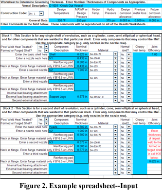
Historic operating conditions can be entered and are used in some circumstances to establish the MAT based on past operations at low temperatures. The input for auto-refrigeration evaluation includes all of the above data plus the vapor pressure curves for the fluids of interest. The spreadsheet includes pre-programmed tables of commonly used carbon and low alloy steels and curves for MAT vs. material thickness and allowable reduction in MAT based on hydrostatic proof testing.
The spreadsheet output, shown in Figure 3, is a plot of fluid vapor pressure and the vessel’s MAT plotted as a function of decreasing pressure. There is a greater risk of brittle fracture for any point of temperature and pressure on the MAT curve above the fluid’s vapor pressure curve.
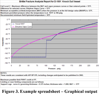
If the point(s) on the MAT curve are below the fluid’s vapor pressure curve, the pressure is within the envelope of acceptable operation. This type of information was used as input to the process hazard analysis to set operating pressure guidelines in the event of an auto-refrigeration incident or re-pressurization limits after an incident.
If the potential exists for the vessel metal temperature to drop below the MAT during an auto-refrigeration incident, there are a number of options that can be considered either alone or in combination.
- Guidelines can be set that limit the operating pressure until the vessel has warmed to the MAT. These guidelines can be used in conjunction with temperature and pressure alarms
- It may be possible to re-hydrotest the vessel at a lower temperature or higher pressure. API 579-1/ASME FFS-1 provides for a reduction in MAT based on hydrostatic proof testing. The allowable reduction is a function of the ratio of design pressure and hydrotest pressure. For example, at a ratio of 2/3 (test pressure = 150% of design pressure) the reduction in MAT is 35F. The hydrotest MAT reduction has a number of qualifiers outlined in API 579-1/ASME FFS-1: 1) it is limited to materials with an allowable design stress of less than or equal to 25 ksi, 2) a maximum primary membrane stress during hydrotest no greater than 90% of the material’s specified minimum yield strength, 3) actual metal temperature as opposed to water temperature is used as the relevant temperature parameter and 4) the MAT cannot be less than -155F after the hydrotest adjustment . There is an increased risk of brittle fracture during hydrotest.
- Post weld heat treatment (PWHT) can lower a vessel’s MAT by 30F for certain materials of construction provided the material thickness is less than or equal to 1.5”. However the adjusted MAT cannot be below -55F. For vessels with no PWHT, it may not be practical to PWHT because of vessel size or other limitations. However local PWHT of a limiting component(s) may be practical and could be accomplished using the Code procedures for local PWHT.
- If the material of construction of a vessel component limits/sets the MAT, it may be possible to upgrade the material. The Code aggregates carbon and low alloy steels into four groups, A through D, based on their resistance to brittle fracture (toughness). Group D materials have better resistance to brittle fracture than Group A materials. The MAT for a material within a group is a function of material thickness with thicker material having less toughness and consequently a higher MAT. For example, 4” thick tubesheet of a Group C material has an MAT of 42F. Upgrading the tubesheet to a Group D material would reduce the MAT to 12F. In our work we have seen cases where tubesheet materials have been upgraded to reduce the MAT. This was done as a part of retubing an exchanger.
- Reduction in MAT is permitted for vessels and components where there is excess wall thickness above that required at design pressure and temperature. API 579-1/ASME FFS-1 provides a curve for determining the reduction in MAT. The curve is a function of weld joint efficiency, governing thickness and past and future corrosion rates.
The spreadsheet considers the hydrotest, PWHT, material group, weld joint efficiency and corrosion allowances in arriving at the MAT and can be used to study the effect on MAT of changes in these parameters.
Recent experience in the evaluation of more than 1500 vessels in four plants showed the spreadsheet tool to be an efficient way to establish the MAT. Although the spreadsheet facilitates the process, the largest time consumer is extracting data typically from older drawings, vessel specification sheets, mill reports, etc.
References:
- 2001 ASME Boiler and Pressure Vessel Code, Section VIII, Division 1, Rules for Construction of Pressure Vessels, 2002 Addenda, Part UCS, Paragraph UCS-66.
- API 579-1 / ASME FFS-1, 2007 Edition, Section 3.
Click to Request Info from Becht


Great article.
The designers of the Titanic would have loved to have know about the effects of cold temperatures in relation to the metallurgic properties before their maiden voyage.
Thank you
Thanks for the in-depth article on generating MAT curves and is very helpful. I tried and done with the equipment part but stuck with piping systems. Appreciate, if you can throw some light on how to proceed with piping systems where valves, flanges, piping supports of different types were used.
For pipes & fittings, I used thicknesses and could generate MAT. Similarly for rated components, calculated stress & co-incident ratios based on ratings. But stuck with generating the MAT curve for entire piping system with supports.
Is it really necessary to check the flexibility of piping systems during depressurization scenarios when lift is not a major concern?