Shaft Fatigue Failures – Part II

Note: This blog is a continuation from the previous article from Becht Engineering, “Shaft Fatigue Failures – Part I”. It is suggested that the reader review “Shaft Fatigue Failures – Part I” before proceeding with this article. Click Here to view Part I.
Before getting into the calculation methods, first a quick refresher on high cycle fatigue. High cycle fatigue failures are typically acknowledged to be fatigue failures resulting from alternating loading cycles in excess of 106 cycles. While that may sound like a large number, in high speed rotating machinery, one million cycles will occur in hours. For high cycle fatigue, the fatigue test data is often reported in the form of alternating stress vs number of cycles (S-N, or Stress-Life method).
Fortunately, many of the common shaft and rotor alloys exhibit a fatigue strength “endurance limit” at about 106 – 107 cycles, beyond which the fatigue strength of the material will remain constant. See Figure 1 for example S-N curves comparing the basic characteristics of ferrous steel alloys vs aluminum. This endurance limit behavior for ferrous materials allows for shaft and rotor designs which will theoretically have “infinite life”, allowing for many years of operation without a fatigue failure.
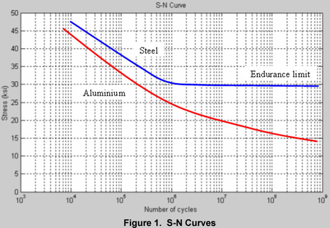
The challenge when performing fatigue calculations in how to relate the specific stress state in question to very simple test data available. The first hurdle to confront when performing fatigue calculations is to understand what (if any) fatigue test data is available. The most common test data available is a simple S-N diagram, such as shown in Figure 1, generated for a specific material in a completely reversed bending loading scenario. One common test method is the R.R. Moore reversed bending test, where a static weight is applied to a rotating shaft. If fatigue test data exists for the particular shaft alloy, this is the best option. However, if fatigue test data is not available for the particular alloy, there are valid correlation methods relating the ultimate tensile strength to the uncorrected endurance limit.
The test data is most often generated with small, highly polished laboratory specimens, and the calculation method needs to introduce various fatigue strength reduction factors based on your specific application. Common correction factors include surface finish, size, type of loading (bending, axial, torsion), surface treatment and environmental conditions. Once these correction factors are applied, you now have the “corrected” endurance limit, which most closely estimates the actual fatigue endurance limit for the particular design being analyzed.
Since most test data exists for laboratory specimens with only an alternating load applied, where no steady state average stress was applied to the specimen, there is a need to understand the impact of nonzero “mean stress” when assessing the fatigue life of a particular shaft design. In most real life scenarios, the shaft, or rotating component is subjected to a complex loading scenario resulting in both alternating and mean stresses. How can this be accounted for in a fatigue life calculation?
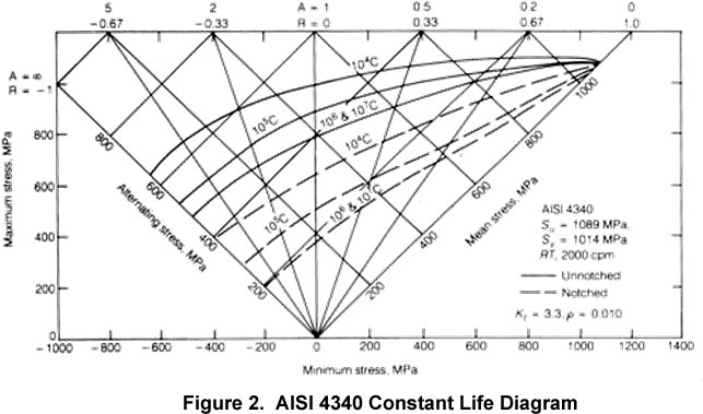
First, in a few cases, there exists a constant life diagram, or Haigh diagram, showing test data correlating the alternating and mean stress – see Figure 2 for an example. As you can see, the constant life diagram clearly shows the relationship between allowable alternating stress vs mean (average) stress. But note, this is most often for a very specific test condition – look to the various specific conditions specified in this diagram before utilizing the test data in a calculation.
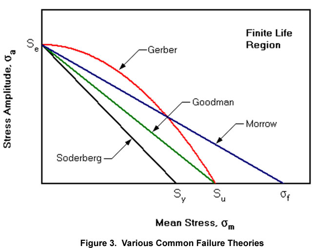
More commonly, constant life diagrams such as figure 2 are seldom available, so we often utilize various failure theories that correlate the fatigue stress limit to either the yield strength, ultimate tensile strength, or fracture stress. Probably the most commonly used method in the US is the Goodman failure criteria, but many others exist. Most test data for common shafting alloys seems to fall between the Goodman and Gerber criteria – see figure 3 for a plot representing some of the more common fatigue failure theories.
Note, for the very common shaft loading scenario of a completely reversed bending load with a steady state torsional load, there exists the ANSI B106.1M “Design of Transmission Shafting” standard outlining a fatigue life calculation method. Also, there are standards such as DIN 743 and the German FKM method commonly used in Europe for analysis and calculation for shafts in fatigue loading. But, as earlier referenced, here in the US, the Goodman failure criteria is one of the more widely used and accepted methods.
The next step in the process involves employing an analytical method to calculate the alternating and mean stress components, at various critical sections. I will not go into this in any depth here, as that is another article by itself, but I typically start out very simple with a free body diagram and simple beam type calculations to estimate forces and moments, etc. From this, analytical methods are employed to derive the various stress components and calculate safety factors based on the Goodman method. It is not uncommon to employ FEA to calculate stress levels to be used in establishing the fatigue safety factor for more complex geometry, but that is not always required.
A couple of final points. Often the question arises as to what is an appropriate safety factor? My experience has been that a 1.75 safety factor is often the starting point. My experience has been that that for most industrial rotating equipment shafts and rotors, this is a “reasonable” safety factor, resulting in minimal risk of fatigue failure. Have I gone with lower fatigue safety factors and still avoided fatigue failures for years of reliable operation – yes, most definitely. It is certainly an experience-based determination of the acceptable minimum fatigue safety factor, but some of the common factors in the decision to either raise or lower the required fatigue safety factor include:
- How accurately can the actual loads be established?
- What is the caliber of material fatigue data available?
- Is this a very simple completely reversed bending loading, or a multiaxial fatigue loading scenario?
- What fatigue life theory have I utilized in the calculation method?
- What is my risk tolerance for the application – i.e., what is the consequence of failure?
- How well can I control operational limits affecting the actual loading?
- How well can I control the environment in operation that might lead to fatigue strength reduction?
Lastly, I have not touched on another very important point – multiaxial fatigue. You will remember from elementary strength of materials that in most beams (and shafts) bending stress governs and shear stress can often be ignored. That is true, but there are certain shaft designs where this is not true. There are some shaft designs for instance, where the shaft geometry results in a very small (L/D) ratio. Here, both the bending and shear stress are significant in magnitude, with the added complexity that the peak bending stress and the peak shear stress occur 90 degrees out of phase with each other. Today, this is a very active area of fatigue research to develop better, more reliable, multiaxial fatigue assessment methods. Again, this is another topic worthy of a separate article. This topic is not covered here other than to make mention of the challenge this presents in certain shaft designs.
Becht Engineering has the in-house analytical methods and experience to help you with your shaft or rotor fatigue evaluations – either as part of new design evaluations or as part of failure investigations.
References:
Bannantine, Conner, Handrock (1990). “Fundamentals of Metal Fatigue Analysis”. Englewood Cliffs, NJ: Prentice- Hall Inc.
[readon2 url=”index.php?option=com_rsform&view=rsform&formId=4&Itemid=739&lang=en”]Contact Becht Engineering to receive more information[/readon2]